
- All
- Product Name
- Product Keyword
- Product Model
- Product Summary
- Product Description
- Multi Field Search
English

Views: 0 Author: Site Editor Publish Time: 2026-06-03 Origin: Site
Improper installation and setup of mixing equipment lead to batch inconsistencies, prolonged mixing times, and premature mechanical wear. Facilities face constant operational bottlenecks and compromised product quality when they ignore proper deployment procedures. You cannot rely on trial and error when configuring industrial blenders. A successful deployment requires precise facility planning, strict mechanical alignment, and process-specific configuration to achieve optimal homogeneity. Specifically, engineers consider a deployment successful when the mixture achieves a Coefficient of Variation (CV) of 10 or less.
We provide an evidence-based roadmap for facility operators and engineers to install, configure, and validate these machines. You will learn how to size equipment correctly based on bulk density and working volume. We detail the mechanical alignments necessary to protect drive systems. Finally, you will discover how to configure internal tolerances and implement strict commissioning protocols before moving to full production.
Base equipment sizing on bulk density and working volume (typically 70-80% of total capacity) rather than overall dimensions.
Mechanical alignment requires exact leveling to prevent main shaft deflection and bearing failure.
Integrate Variable Frequency Drives (VFDs) to manage startup torque and fine-tune shear.
Match discharge valve configurations (e.g., slide gates vs. bomb bay doors) to the specific material's flow and sealing requirements.
Mandate strict commissioning protocols, including dry-run tests and graded material feeding phases, before moving to full production.
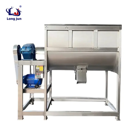
Mismatched facility infrastructure and equipment footprint cause integration delays and operational bottlenecks. You cannot simply drop heavy machinery onto a factory floor and expect perfect operation. Engineers must plan volumetric capacity and structural limits well in advance. Ignoring these preliminary steps often leads to restricted maintenance access and inefficient loading sequences.
Sizing relies on a specific volumetric formula rather than physical machine dimensions. Define the sizing formula to ensure adequate particle movement space. The formula states: Total Mixer Size = Batch Volume / 0.7. This calculation leaves necessary head space above the agitator. Without this empty space, materials cannot lift and fold properly.
Bulk density heavily influences motor and structural choices. Differentiate standard vs. heavy-duty motor configurations based on the material's bulk density. Standard models typically handle around 0.5 to 0.6 kg/L. If you process dense minerals or heavy metallic powders, you must specify a heavy-duty drive. Failing to upgrade the motor for dense materials guarantees frequent stalling and severe mechanical strain.
Evaluating spatial parameters prevents costly facility modifications later.
Evaluate structural load-bearing capacity for the dynamic weight of a fully loaded powder horizontal belt mixer. Dynamic loads during operation far exceed the static weight of the machine.
Ensure ample overhead clearance for automated loading systems and bulk bags.
Verify you have sufficient sub-floor access or elevated platforms for discharge stations.
Addressing the physical placement and foundational integrity determines the long-term reliability of your equipment. A weak foundation amplifies operational vibrations. These vibrations loosen fasteners and misalign drive components over time. You must anchor the equipment to a reinforced concrete pad.
Detail the necessity of strict level placement for a U shaped screw belt mixer to prevent shaft deflection and uneven ribbon wear. Even a slight tilt causes gravity to pull the massive central shaft out of alignment. This deflection grinds the outer agitator against the trough wall. Use precision machinist levels or laser leveling tools across the main shaft before securing the anchor bolts.
Drive systems have evolved significantly from older industrial designs.
Specify the transition from legacy chain or belt drives to direct-drive gearmotors. Direct drives drastically reduce maintenance intervals and eliminate power loss from slipping belts.
Require the integration of Variable Frequency Drives (VFDs) to mitigate high startup torque. Soft starts protect the gearmotor from catastrophic sheer stress.
Use the VFD to allow exact RPM tuning. The standard baseline ranges from 20 to 50 RPM. You should aim for a Froude number below 1. This ensures a gentle, convective folding action rather than aggressive centrifugal throwing.
Powder processing inherently generates dust, creating severe explosion risks. For dust-prone environments, strictly adhere to ATEX directives. Ensure outer tip speeds remain below 1 m/s to prevent static ignition. Verify the installation of pressurized bearing seals. These seals use compressed air to block combustible dust from entering the bearing housings. They effectively mitigate combustible dust explosion risks.
Selecting the right internal and external configurations directly impacts your process goals. We evaluate dimensions based on features-to-outcomes. Every mechanical feature must serve a specific mixing objective. You must audit internal clearances, fill volumes, and valve types before running the first batch.
Verify mechanical tolerances during the setup phase. State the industry standard of 3 to 5mm clearance. This translates to roughly 1/8" to 3/16". Maintaining this tight gap drastically minimizes residual dead zones. Unmixed ingredients gather in wide gaps, ruining the overall batch homogeneity. However, clearances tighter than 3mm risk metal-on-metal contact if thermal expansion occurs.
Establish the precise fill volumes required to ensure the inner and outer ribbons engage the material effectively. Establish a minimum fill rate of 30% to 40%. Dropping below this threshold prevents the agitators from grabbing the powder. Establish a maximum fill volume of 70% to 80%. Overfilling restricts the vertical cascade effect necessary for true blending.
Matching the discharge valve to your material prevents leaks and speeds up processing times.
Valve Type | Primary Benefit | Best Application Scenario |
|---|---|---|
Drop Bottom / Bomb Bay Doors | Rapid discharge (<30 seconds) | High-throughput lines needing zero cross-contamination. |
Slide Gates | Superior sealing capabilities | Handling ultra-fine powders prone to leakage. |
Sanitary Round Valves | Eliminate internal dead spots | Food and pharmaceutical compliance requiring easy cleaning. |
Modifying standard setups becomes necessary when handling complex mixtures. Standard configurations fail when you introduce liquid integration or shear-sensitive materials. You must adapt the internal geometry and delivery systems to prevent product degradation.
Adding liquids to dry powders easily creates stubborn lumps. Mandate atomizing spray bars paired with precise metering pumps. You must avoid manual pouring entirely to prevent agglomeration. Atomizing nozzles distribute fine droplets evenly across the shifting powder bed. Highlight the critical distinction between specifying "dust-tight" versus "liquid-tight" discharge valves when wet mixing. Standard dust-tight valves will leak liquid ingredients, creating unsafe workplace conditions and inaccurate formulations.
Evaluate when to swap traditional double ribbons for paddle-style agitators. Ribbons create intense shear forces near the trough walls. They often form pinch points that crush fragile ingredients. They also alter irregular particle shapes undesirably. Paddles offer a scooping and lifting motion. This gentle agitation protects delicate structures while maintaining rigorous homogeneity.
Establishing verifiable proof of performance before production release guarantees operational trustworthiness. You must document every testing phase. Skipping these steps leads to unexpected failures during critical production runs.
Phase 1: Dry-Run Testing. Run the empty equipment to inspect for unusual vibrations. Monitor the control panel for motor amp spikes. Listen carefully for mechanical grinding, which indicates poor shaft alignment.
Phase 2: Material Feeding Test. Incrementally load materials into the trough. Practice layering ingredients vertically rather than dumping them all at one end. Observe the axial mixing efficiency. Monitor the drive system for unexpected motor strain as the load increases.
Quality Assurance Metrics. Sample the finished batch from multiple zones. Confirm the mixture achieves a Coefficient of Variation (CV) of 10 or less. You should accomplish this within the projected 5 to 20 minute mixing cycle.
Identifying standard failure points during the first 90 days of operation prevents catastrophic breakdowns. New equipment experiences a break-in period where fasteners may loosen and seals may settle. Vigilance during this early phase secures long-term reliability.
Establish a strict schedule for bearing lubrication and air-purge seal checks. Bearings bear the entire dynamic load of the shaft and product. They require premium food-grade or industrial lubricants. Pressurized seals require continuous clean air flow. If the air pressure drops, abrasive powders enter the bearing housing, destroying the mechanical components rapidly.
Understanding common symptoms helps operators resolve issues without calling costly technicians.
Motor stalling: This failure is usually caused by overloading the vessel beyond its bulk density specifications. It also occurs if operators attempt starting under full load without utilizing a VFD.
Extended mix times: This symptom is often a symptom of running RPMs too low. It also arises from incorrect ingredient loading sequences. Always load major base ingredients first, followed by minor additives.
Precise installation parameters dictate final product consistency. You must control mechanical clearances, integrate VFDs correctly, and respect volumetric fill rates to achieve optimal homogeneity. A well-installed machine runs quietly, seals perfectly, and delivers a CV of 10 or less consistently. Deviating from these engineering baselines guarantees operational headaches.
Advise buyers to require vendor-supplied Factory Acceptance Testing (FAT) documentation. You should request certified dimensional drawings early in the planning phase. Demand a documented mechanical tolerance sheet prior to finalizing the equipment sign-off. These documents prove the manufacturer met all required specifications before the machine left their facility.
A: The ideal fill level strictly falls between 30% and 80% of the total volumetric capacity. You need a 30% minimum to ensure the agitator engages the powder effectively. You must observe a 70-80% maximum to allow enough head space for material lift and folding during the cycle.
A: Prevent dead zones by verifying a strict 3-5mm clearance between the outer agitator and the trough wall. Additionally, selecting a flush-fitting bottom-discharge valve, such as a drop bottom or sanitary round valve, eliminates unmixed powder pockets at the discharge point.
A: Yes, but you must modify the standard setup. Install atomizing spray bars and precise metering pumps to distribute liquids evenly and prevent lumps. Furthermore, you must upgrade the bottom discharge valves to fully liquid-tight configurations to prevent hazardous seepage.
A: Extended mixing times usually result from incorrect operating parameters. Common causes include running the RPM too low, an incorrect Froude number, or an improper ingredient loading sequence. Overfilling the trough beyond 80% also severely restricts particle mobility, delaying batch homogenization.


